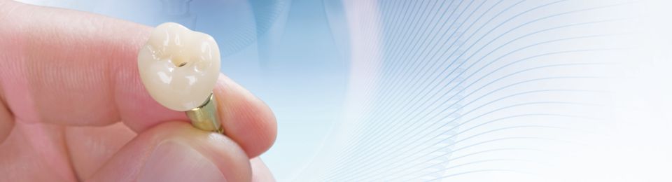
Implant-supported restoration made of VITA ENAMIC IS
At IDS 2015, the VITA IMPLANT SOLUTIONS (IS) blanks with an integrated interface to a titanium/adhesive base (e.g. TiBase) for implant-supported crown restorations were introduced for the first time. PD Dr. Andreas Bindl shows in his case report the treatment of a patient with VITA ENAMIC IS in the lateral region.
1. Initial situation
A 75-year-old patient came to our practice for the prosthetic treatment on two implants (Biomet 3i, Palm Beach Gardens, USA) in regions 25 and 26. After three months of closed healing, the soft tissues were healthy (Fig. 1), and the implants were completely osseointegrated (Fig. 2). The plan was to expose and prosthetically restore the implants within one treatment session. This has the advantage, in addition to the general time and cost savings associated with chairside treatment, that there is no repeated manipulation of the soft tissues. This procedure has only been feasible since the introduction of the CEREC Software Version 4.2 (Sirona Dental, Wals, Austria).
2. Digitalizing and design
First, the implants were exposed and compatible scan posts and scan bodies (Sirona Dental) were fixed to these (Fig. 3 and 4). The correct position was examined with the aid of an x-ray image (Fig. 5). Then, the digital molding (CEREC Omnicam, Sirona Dental) of the situation was performed using scan bodies, followed by scans of the antagonists as well as the buccal bite registration. The 3D model was calculated, and the one-part abutment crowns constructed, taking into consideration all relevant information with the CEREC Software V 4.4 (Fig. 6 through 8).
3. Manufacture and integration
After milling in the CEREC MC XL milling unit, the VITA ENAMIC IS crowns were reworked and polished extraorally with the instruments of the VITA ENAMIC Polishing Set. Bonding on the TiBase was done according to the manufacturer's instructions with the Multilink Hybrid Abutment (Ivoclar Vivadent, Schaan, Liechtenstein). After insertion, the crowns showed a precise fit (Fig. 9) and fit well into the overall picture (Fig. 10 and 11). Figures 12 and 13 show the result after four weeks. The gingiva is well healed, but it still has to form a tight gingival collar around both abutment crowns.
4. Summary
With VITA ENAMIC IS blanks, direct screw-retained implant-supported restorations can be manufactured and integrated within one treatment session. Hybrid ceramics also exhibit a modulus of elasticity that is similar to that of dentin. To what extent this results in a reduction in masticatory forces applied on the implant and whether this will positively impact the survival rate of implant-supported restorations is currently being studied.
Report 09/15